What the instrument does
An imaging caliper goes down an oil or gas well and measures the shape of the borehole as it travels. The MFC40C-G does this with 40 spring-loaded fingers spread around the tool. Each finger presses against the well wall, and its position is measured by an LVDT, a transformer whose output changes as a core moves inside it. Read all 40 fingers together, many times per second, and you get a picture of the inside of the well: corrosion, deformation, buildup.
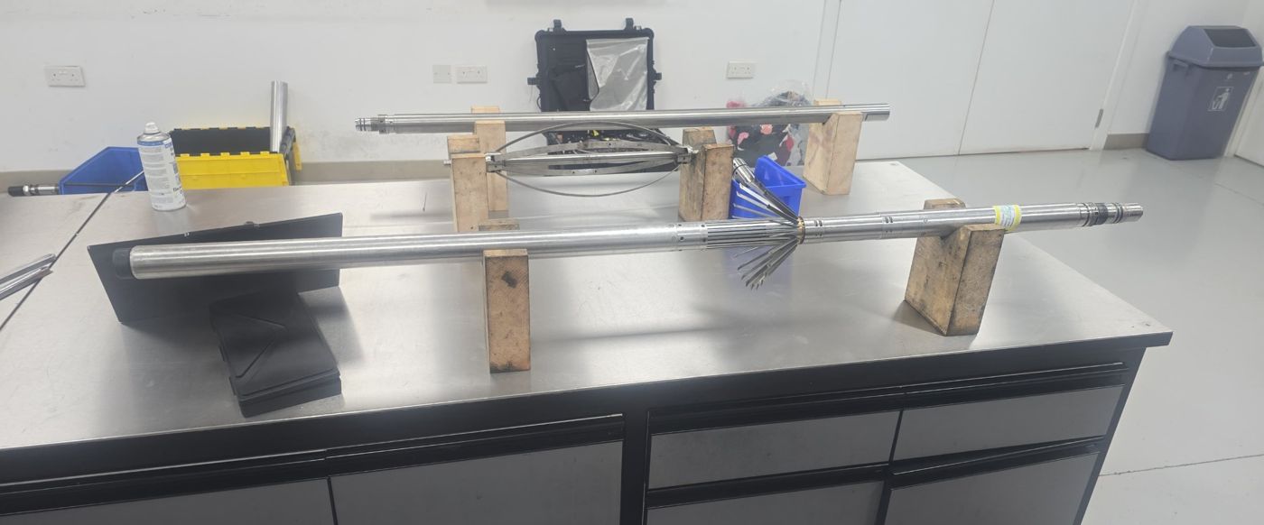
GOWell builds and services these tools for oilfield service companies, including SLB, Halliburton, Baker Hughes and Weatherford. Over the internship I worked with 12+ electromechanical tools on the bench. This caliper was the one I got to know best.
The signal chain
To find a fault, you first need to know what a healthy signal looks like at every stage. Here's my simplified version of the measurement chain. Click a stage to see what it does and what I checked there.
Click or tab through the stages. The red outline marks where the fault turned out to be.
Tracing the fault
The symptom. One finger channel read at full scale no matter where the finger was. Every other channel behaved normally.
The approach. Rather than swapping parts and hoping, I worked through the chain one stage at a time:
- Used the wiring diagrams to map exactly which connectors, traces and components that one channel passes through.
- Measured the signal with an oscilloscope at points along that path and compared it with the same points on a healthy channel.
- Found where the healthy and faulty paths stopped matching, and used what I knew about each stage to work out which part could cause what I was seeing.
- Narrowed it to a signal-processing IC in the conditioning stage.
The result. The IC was replaced, and the channel came back with normal readings.
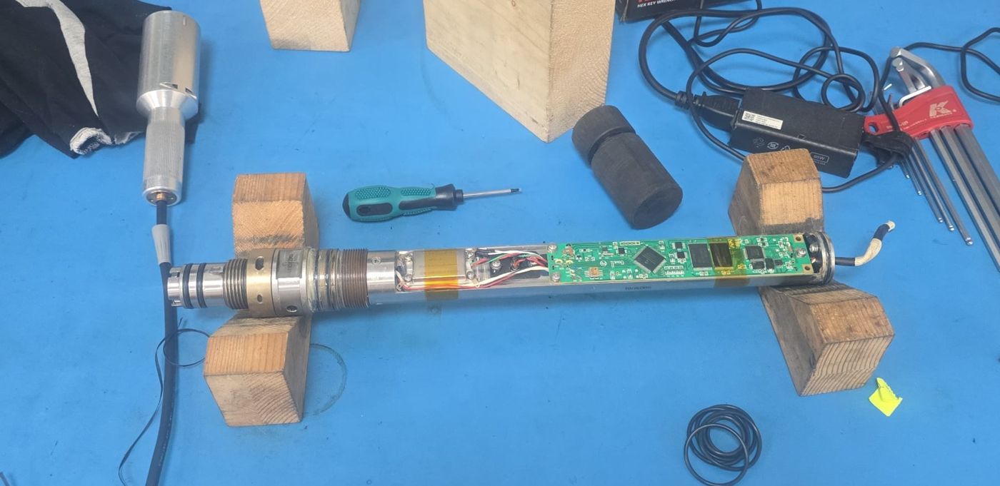
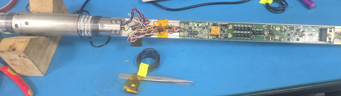
What I did
- Scope measurements and signal tracing
- Reading the wiring diagrams and mapping the channel
- Isolating the fault to the IC
- Supporting the repair and retest
What I didn't do
- The SMD replacement of the IC itself
- Design any part of the tool. I diagnosed an existing commercial design.
Calibration and verification
Electronics drift with temperature, and downhole tools get very hot. I helped collect the data used to correct for that:
- Placed the tool in a hot-air oven and stepped the temperature in increments of about 10 °C.
- At each step, set the fingers to known positions with fixtures and recorded the raw sensor counts.
- Ran continuity checks before and after each run, so a wiring fault couldn't masquerade as sensor drift.
It's slow, careful work, and it showed me how much of real engineering is verification.
What I learned
I also sat in on other investigations, including an EPDT tool with a suspected secondary-coil fault, and observed MCS equipment being tested. I was there mostly to learn on those, so I don't count them as my work.