Try it
Press play, then flip the farm-road sensor and watch how the controller responds. Time runs 6× faster than on the board.
The simulator shows the behavior I designed for. The yellow and all-red times are shortened for the demo. See what I'd change for one place where my RTL didn't fully match this behavior.
How it's built
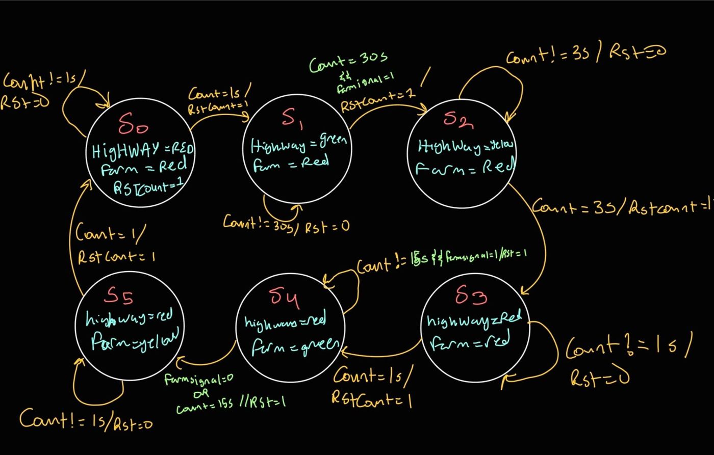
The design has two levels. tlc_controller is the top level: it owns the 31-bit timer counter, synchronizes the reset button, and exposes debug signals. Inside it, tlc_fsm decides the state and the light outputs from the timer value and the farm-road sensor.
- Two-block FSM style. Next-state and output logic live in a combinational
always @(*)block with blocking assignments. The state register updates on the clock edge with non-blocking assignments. Keeping them apart avoids simulation races and makes the hardware intent obvious. - Timer reset handshake. When the FSM changes state, it raises
RstCountfor one cycle, and the controller zeroes the counter. Each state measures its own duration from zero, as a multiple of the 50 MHz clock (50,000,000 cycles is one second). - Reset synchronizer. The reset is a physical push button, asynchronous to the clock, so it passes through a two-flip-flop synchronizer before it reaches the state register.
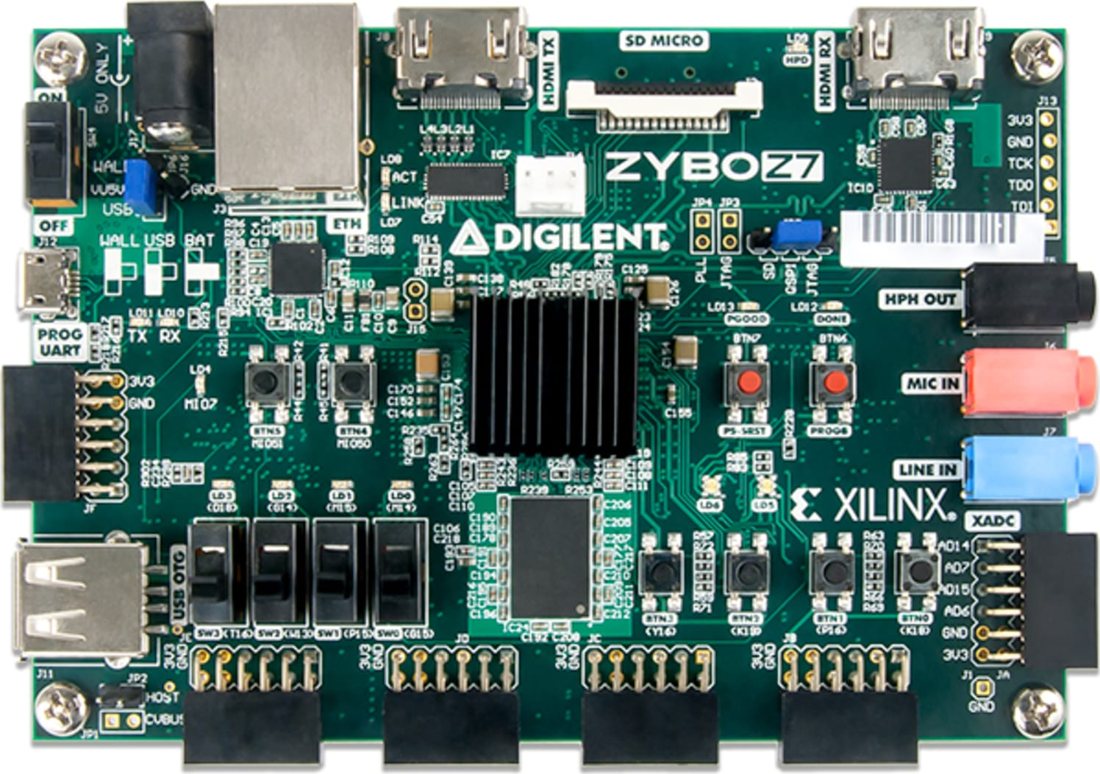
- Debug pins. The current state and the counter-reset pulse are routed to Pmod header JB, so I could watch the FSM from outside the chip while testing on the board.
The RTL
The two states that make it sensor-aware:
S1 : begin                       // highway green
    highwaySignal = Grn; farmSignal = Red;
    if (Count == D1 && farmSensor == 1) begin
        RstCount = 1; nextState = S2;  // minimum green served, car waiting
    end
    else begin RstCount = 0; nextState = S1; end
end

S4 : begin                       // farm green
    highwaySignal = Red; farmSignal = Grn;
    if (Count == D4 && farmSensor == 0 || Count == D5) begin
        RstCount = 1; nextState = S5;  // road empty, or max time reached
    end
    else begin RstCount = 0; nextState = S4; end
end
The light outputs are assigned at the top of every state branch, so every path through the combinational block drives every output. That's what prevents Vivado from inferring unwanted latches.
What I'd change now
Looking back at this design with fresh eyes, there are three things I'd fix:
- Compare with ≥, not ==. The transitions check
Count == D1. If a car arrives a moment after the counter passes 30 s, that exact value never comes around again until the 31-bit counter wraps, about 43 s later. UsingCount >= D1would serve that car right away, which is the behavior the simulator above shows. - Synchronize the sensor too. I synchronized the reset button but fed
farmSensorstraight into the FSM logic. It's just as asynchronous, so it should get the same two-flop treatment. - Name the delays by time. The delay constants are raw cycle counts. Defining them as seconds × clock frequency would make the timing obvious at a glance and harder to get wrong.
Datapath and ARMv8 (Computer Architecture)
In ECEN 350 I worked from both ends of the hardware/software boundary.
ARMv8 assembly
- Loads, stores and conditional branches
- Function calls with correct stack frames and link-register save/restore
- Recursive routines, including a recursive power function
- Debugging control flow and stack corruption
Verilog datapath parts
- 64-bit ALU
- Register file
- Sign extender for I-, D-, CB- and B-type immediates
- 8-bit 2:1 mux, each part with its own testbench, checked in GTKWave
Writing the sign extender taught me why the ARM instruction formats look the way they do: each one packs its immediate into different bit positions, and the hardware has to know which format it's looking at before it can extend the value.